|
March 19, 2002
|
||
 |
meshANT-S v2.0d and greater |
|
|
March 19, 2002
|
||
|
meshANT-S v2.0d and greater |
|
The meshANT-S grid generator is designed to be a simple tool to create surface and wire grids from canonical shapes using a script. The script features simple expression evaluation with local variables and the ability to write and use library functions. The former enables parameterized models while the latter allows for versatile reuse of grid parts. Tolerance values (two types) can be used to merge grid points and eliminate small elements to give you nice grids. The scripts run very fast, so go ahead and use the run button often while writing the script to verify your progress. For interested users, the interface utilizes the cross-platform FLTK library. The user interface is composed of three pieces: a menu bar across the top, a panel to edit scripts, and a panel to view the grid. A thin vertical bar between the two panels can be moved with the pointer to adjust the space allotted to each. Take a peek at a screen shot, if you'd like. The script editor has emacs-like shortcuts for keyboard navigation and cut/copy/paste features. Table II shows the full list of shortcuts. Comments can be interspersed throughout the script. Each starts with a '#' or '!' character and extends to the end of the line. The two choices have identical effects, but offer a heavy- or light-weight visual impact to the comments for those who have preferences. Each free-formatted command in the script starts with a key word representing an action or the name of a builder. Currently the actions are set, include, define, build,and repeat. Respectively, they set a parameter value, include an external file, define a library object, build a library object, and run a script a specified number of times. The current list of 1D/2D builders include line/plate, arc/cylinder, and orbit/sphere for paths/surfaces in Cartesian, cylindrical, and spherical coordinate systems. The syntax for each builder is simple: the builder name followed by a name for the resulting grid, the number of subdivisions to create, and the coordinates for each vertex. The 1D builders require a single value for the number of subdivisions and two vertices (six values); the 2D builders need two values for the subdivisions and four corner vertices (12 values). The ordering of the four vertices defines the perimeter of the grid, and, using the right-hand-rule principle, defines the top side of the surface. Thus, a simple 2x2 rectangle with top side pointing int the +z direction can be built with the command plate my_rect 2 2Define parameters and use them in the script to facilitate consistent meshes.When an object is built it uses the current values of any necessary parameters. In particular, meshants uses a set of predefined parameters to establish the current origin, rotations, element type, color, and merging tolerance. You can set and use as many other parameters as you wish and use them in mathematical expressions. The case-sensitive parameter names can be of any length, but may consist only of letters from the alphabet, numbers, and the characters '.' and '_'. The '.' character is used in several of the predefined parameters to name their individual component values. For example, the x component of the origin is origin.x. A complete list of the components of the predefined parameters can be viewed from the INFO menu item SHOW PREDEFINED. Expressions can be used anywhere a numerical value is expected, but must be enclosed in square brackets. A parameter's value is accessed in an expression by preceding its name with a '$'. An expression can use any of the mathematical operators '+', '-', '*', '/', and '^', and multiple levels of parentheses. The '^' operator is for exponentiation which would have been '**' in FORTRAN programs. Expressions may also use standard mathematical functions (sin, cos, tan, asin, acos, atan, exp, log, sinh, cosh, sqrt, abs, ceil, floor, j0, j1, y0, y1). A word of caution: all numerical values are treated as floating point values so [4*(1/2)] will yield 2.0 not 0 since the (1/2) is not 0 but 0.5. As an example, to create a cone-shaped mesh with the diameter equal to the height the following would work: set h .3 cylinder myCone 2 18 ! yields 2 x 18 subdivisions 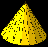 The
result of the above commands will set a parameter 'h'
to 0.3 and then invoke the cylinder
builder to create a grid 2x18 in size (image at right used the default triangle
element type). The four vertices are given in cylindrical coordinates. Note
that both the radial and height coordinates change in unison along the first
and third sides of the perimeter (i.e., in the "I" direction) and
the azimuthal angle changes in the "J" direction (see the second and third
vertices). The height of the cone (I direction) is subdivided into two segments;
the J direction is subdivided into 18 azimuthal segments of equal size.
The merging of points and elimination of collapsed elements is apparent
at the apex. The
result of the above commands will set a parameter 'h'
to 0.3 and then invoke the cylinder
builder to create a grid 2x18 in size (image at right used the default triangle
element type). The four vertices are given in cylindrical coordinates. Note
that both the radial and height coordinates change in unison along the first
and third sides of the perimeter (i.e., in the "I" direction) and
the azimuthal angle changes in the "J" direction (see the second and third
vertices). The height of the cone (I direction) is subdivided into two segments;
the J direction is subdivided into 18 azimuthal segments of equal size.
The merging of points and elimination of collapsed elements is apparent
at the apex.
Parameterized builders are included for each of the above canonical builders. The paramterized versions are: pline/pplate, parc/pcylinder, and porbit/psphere. The syntax for these is slightly different; instead of specifying the objects vertices you must provide three expressions, one each for the three components of the coordinate system. For the one dimensional objects a simplex coordinate named 's' is available and varies from 0.0 to 1.0 with the specified number of subdivisions. For the two dimensional objects, simplex coordinates 'u' and 'v' are available and vary from 0.0 to 1.0. They are subdivided, respectively, by the first and second subdivision numbers that follow the object's name. While very versatile, these parameterized builders run more slowly than their canonical cousins because the final coordinates are computed in the interpreter. The rectangle in the first example above can be built with the command pplate my_rect 2 2During the construction of a parameterized grid, the simplex coordinates ('s', or 'u' and 'v') will hide similarly named parameters you may have defined. However, the original values will be restored as the construction is completed. Of the other commands, the include <file_name> command is rather straightforward. The file name is treated as a path name relative to the including file (or current working directory if the script is not yet associated with a file). Thus, an included file can include another file, the latter is treated relative to the former. Absolute file names work equally well. The define/build pair of commands require a little explanation. The syntax for the define command is define any_name { <your script> }. The braces are used to delineate the body of the library function you named any_name. The library function can have arguments passed into it. These are numerically named and can be accessed in expressions as $1, $2, etc. The build command syntax is build any_name <arg1> <arg2> ... ;. The semicolon terminating the argument list is important and must be used even when there are no parameters -- if it can't be found the interpreter will let you know. The repeat <count> {<your script>} command will execute the script the given number of times. If you want to use an incrementing variable within the repeat command you must establish it prior to the command and then increment it within the script body; the repeat command does not pass its index. There are no restrictions on the content of scripts in the define and repeat commands. Errors in your scripts are gracefully caught and terminate the interpreting process and then pop up a helpful message. Most errors will be related to syntax; if you're having trouble remembering the syntax for a command, type in a guess and let the error message help you out. If you've misspelled the object's canonical type (e.g., typed 'lin' instead of 'line') a list of available types will be accessible from a button in the informational window. For the less daring, there is a bit of helpful information in the INFO menu. For added insurance, anytime you cause your script to be closed (e.g., when opening another or quitting) you will be offered a chance to save it. The grid viewer in the right hand panel is used to visualize the resulting grid. It has a pop up menu accessed with the right mouse button and includes a HELP option that describes how to interact with it. For the best experience, a 3-button mouse should be used. The keyboard, too, can be used to manipulate the geometry. For example, there are keys to ROTATE and ZOOM the graphics. A particularly useful feature is the ZOOM INTO key that invokes the AUTO_SCALE and AUTO_ZOOM using only the grid object under the mouse pointer rather than the whole geometry. As with the mouse button bindings, see the HELP menu for the keyboard bindings. You can also keep tabs on the effects of setting tolerances: toggle on/off SHOW POINT MERGING in the INFO menu of the main menu bar. The grid viewer will overlay red line segments showing where points have merged from. Sorry, no graphics printing is available yet. OpenGL is based on rasterization and your screen's resolution is many times lower than a printer's. You can use screen captures or window dumps, but they will only yield "web" resolution graphics. The menu bar contains the traditional FILE menu that has commands for opening, saving, and closing scripts, and an entry for quitting. The actions performed by these menu items are linked: quitting via the menu item or window manager will close the script first; opening a script will also close the current script first; and closing a script will offer you the chance to save it first. Also in the FILE menu is an EXPORT option for generating a grid file. If your desired format is not available please contact ANT-S for a new format. The INFO menu contains commands for viewing information about the available builders and commands, the predefined parameters and their default values, the recent parameters (values after the script is finished), and the editor's shortcut keys. The exact list of builders and actions available at runtime, obtained from the INFO menu, will always be up-to-date even it the documentation is not. One additional item appears on the main menu bar: a RUN button that initiates the parsing of the script. Remember, don't worry about mistakes in the script; errors generate informational dialog windows and interrupt the processing. While the approach is fairly robust, the location of the error is not highlighted. Future versions may take you right to the spot. The file selection dialog is rather unique, but very functional. Its key feature is its dynamic matching of your typed entry to existing files or directories. As you type, only those possible choices matching your entry are shown. Pressing the 'tab' key will complete your typing for you up to any unique characters in the reduced list -- if only a single entry is remaining its full value will be completed for you. This combination of filtering and completion can be used to rapidly navigate around a file system without using your mouse. The remaining interface elements in the dialog should be familiar to all so they are not discussed here. Table I. Predefined Parameters and their definitions.
Table II. The script editor interface.
Screen shot of a short script creating a sphere, with a hole in it, from quadrilaterals. Notice that right-handed spherical coordinates use R,q,f (i.e., radius, latitude, longitude). Here, the starting latitude is 20 degrees and extends to 180 degrees. The longitude ranges the full range of 0 to 360 degrees. The ordering of the four vertices traces out the perimeter first along the 20 degree latitude, then to the South Pole and around it, and then implicitly back to the start. Thus, the grid has 36 longitudinal subdivisons and 18 in latitudinal subdivisions; you can see all 36 subdivisions around the hole. 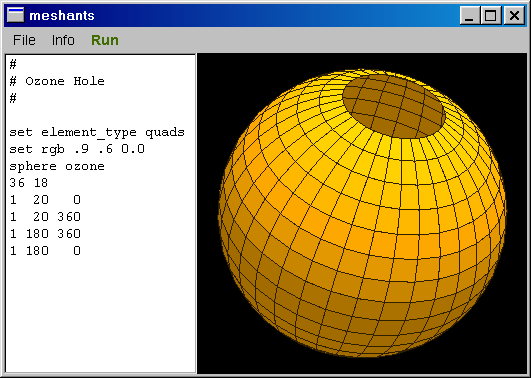 |